Installing a 5975/5976 Customer Display
The terminal supports two customer displays.
•NCR 5975 Graphical Customer Display (VFD)
•NCR 5976 Remote Customer Display (LCD)
There are four different length posts available, in four inch increments.
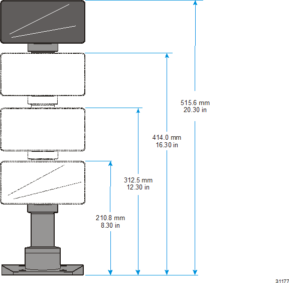
Note: Heights greater than 215 mm (8.5 in.) should be screwed to the counter top.
1.Locate the Display Mount within 4 meters (13 ft.) of the host terminal.
2.Determine if the cable should be routed down through the mounting surface or if it should be run on top of the surface. Drill a hole if necessary.
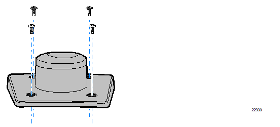
3.If you are installing with a post greater than 215 mm (8.5 in.) secure the Base Plate with screws (4) that are appropriate for the surface that you are installing the Base Plate to.
4.Connect the Interface Cable to the Display Module, either RS-232 or USB.
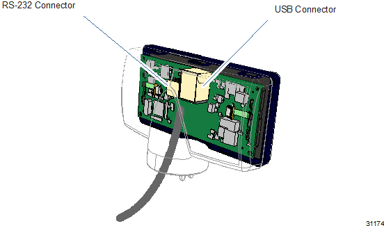
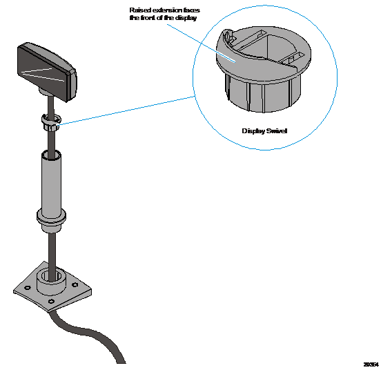
5.Route the Interface Cable through the Post and assemble the Post components.
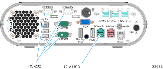
6.Connect the Display Cable to the terminal.
RS-232 Interface
Connect the I/F cable to a powered RS-232 connector on the terminal.
Note: The factory default settings for the COM1 and COM2 ports are powered by default. To change a port to non-powered see the Powered Serial Port Settings appendix.
Configure the terminal serial port as follows:
9600 baud, 8 data bits, 1 start bit, 1 stop bit, No parity
USB Interface
Connect the I/F cable to the powered 12V Powered USB connector on the terminal.